Loading practice lab…
Reading P&IDs
What a P&ID Actually Is
A Piping and Instrumentation Diagram (P&ID) is a schematic showing the pipes, valves, pumps, vessels, and instruments in a system, along with how they're connected — not to scale, not showing physical layout, but showing process connections in enough detail to understand how the system works. Where a plant photo shows you what equipment looks like, a P&ID shows you how fluid gets from one piece of equipment to another, through which valves, monitored by which instruments. It's one of the most important documents for genuinely understanding a system rather than just recognizing its equipment.
A P&ID can omit minor details, and field modifications sometimes outpace drawing updates. Always check that you're looking at the current approved revision, and treat the drawing as a guide to verify against actual field conditions and your plant's procedures — not as an unquestionable substitute for what's physically installed.
Every plant system module in this course (BTA-105 through BTA-107) gave you a simplified visual diagram to learn the big picture. A real P&ID is denser and more literal — but once you can read one, you can trace exactly what happens if a specific valve is closed, which is a genuinely different and more powerful skill than recognizing equipment by sight.
Valves: The Symbols You'll See Most
Different valve types are drawn with distinct symbols because they behave differently, and knowing which type you're looking at tells you something important before you ever touch it:
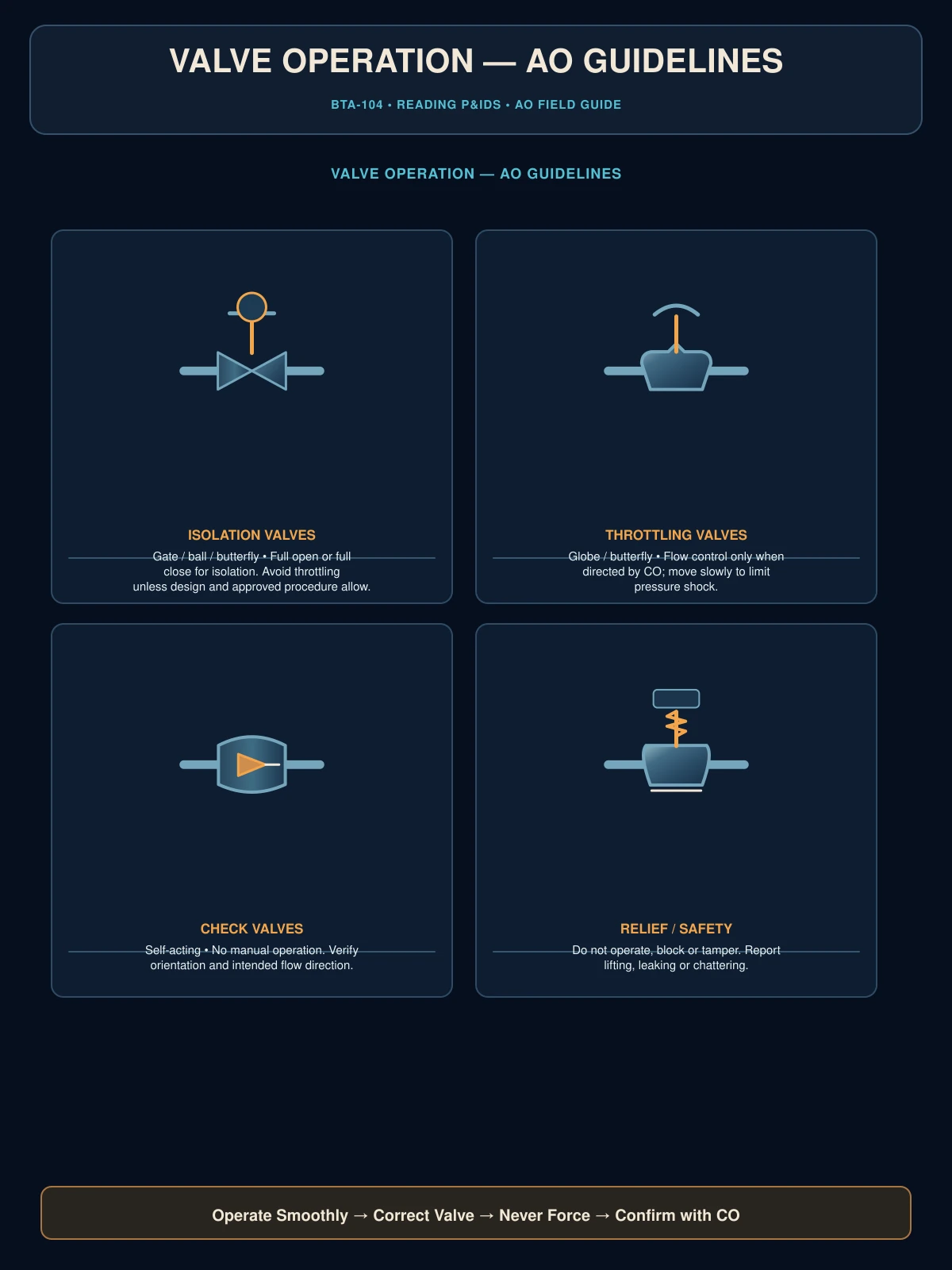
- Gate valve — drawn as two triangles meeting point-to-point. Fully open or fully closed only; not meant for throttling flow.
- Globe valve — a valve body design (named for its rounded body shape) suited to throttling as well as on/off service, distinct from a gate valve's design. Globe valves can be manually operated or automated.
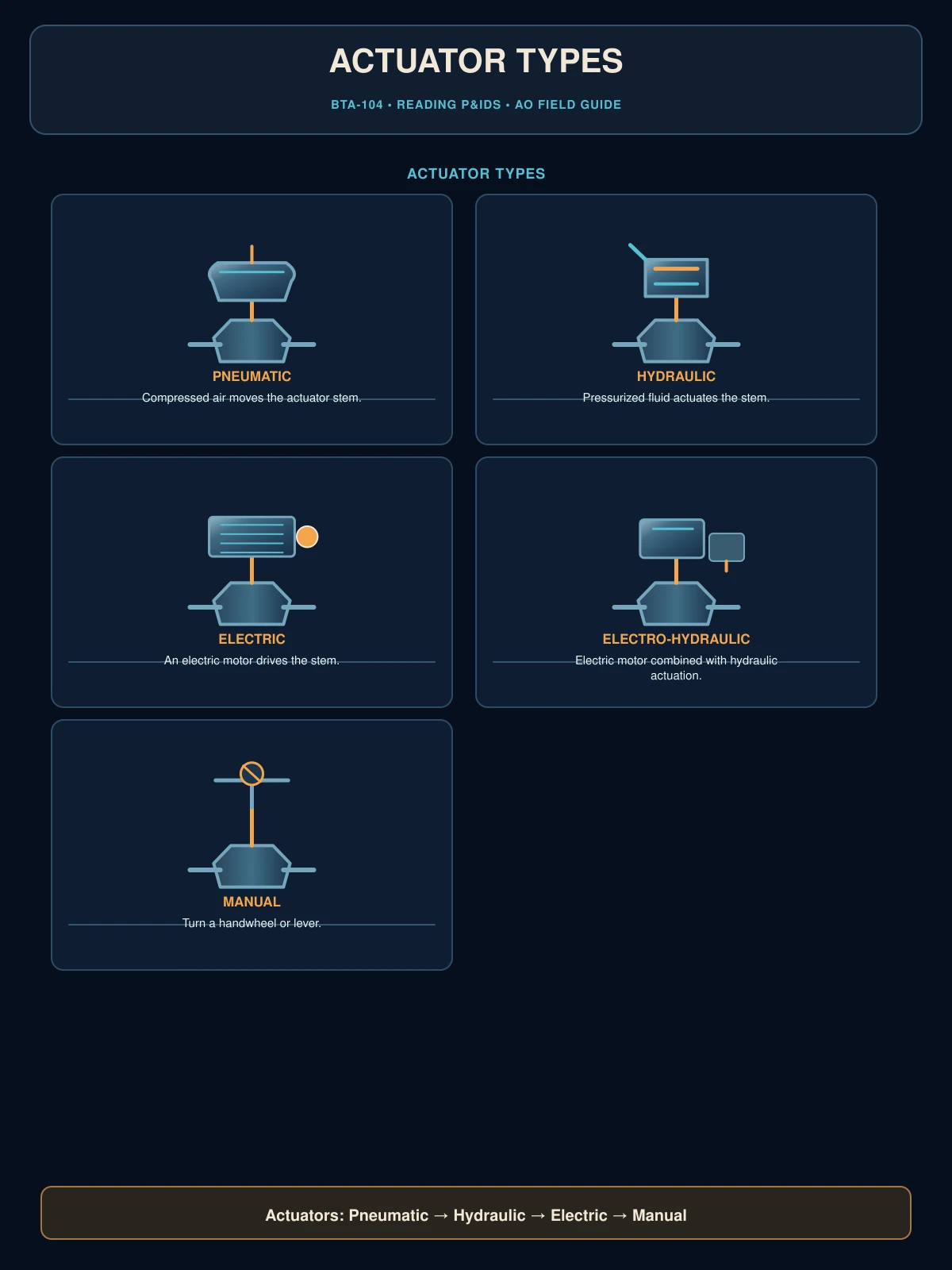
- Control valve — not a body design but a function: any valve (commonly globe-bodied, but not always) fitted with an actuator and automatically positioned by the control system, frequently used to throttle flow to a specific setpoint. The actuator symbol on top (often a small box or diaphragm shape) is what marks a valve as a control valve on the drawing.
- Check valve — a circle with an internal arrow or flapper shape, allowing flow in only one direction and automatically preventing backflow.
- Relief/safety valve — a distinct symbol (often a triangle-like shape with a spring representation) protecting equipment from overpressure by opening automatically above a set pressure.
Instrument Bubbles
A circle (sometimes called a "bubble" or "balloon") on a P&ID represents an instrument, with letters inside identifying what it measures and does. The letters follow a standardized code (ISA notation): the first letter typically identifies the measured variable, and following letters identify the function.
FIC-118 = Flow Indicating Controller, loop 118
LSH-302 = Level Switch High, loop 302
Common first letters: P (pressure), T (temperature), F (flow), L (level). Common following letters: T (transmitter), I (indicator), C (controller), A (alarm), S (switch). Once you know this code, an unfamiliar instrument tag stops being a mystery and becomes readable at a glance.
Lines, Crossings, and Junctions
This is where people new to P&IDs make the most costly misreading mistakes: on most drawings, when two lines cross, they are not connected unless a junction is explicitly shown — typically a solid dot at the intersection, or a small jog in one line to visually indicate it passes over/under the other. This convention can vary between drawing standards and companies, so always confirm against the specific drawing's legend rather than assuming. Assuming two crossing lines are connected when they aren't (or vice versa) leads to a fundamentally wrong understanding of how a system is actually piped.
Before you rely on a P&ID to understand a system, especially before any lineup or isolation activity, verify every junction relevant to your task explicitly. Don't assume; confirm what the drawing is actually showing at each crossing point.
Equipment Tags
Every piece of equipment on a P&ID has a unique tag number, typically combining an equipment type prefix with a unique number, and sometimes a letter suffix distinguishing redundant equipment (P-101A and P-101B for two pumps performing the same duty). Tag prefix conventions vary by facility — one plant's "P" for pump and "V" for valve might be a different plant's "V" for vessel, with valves numbered a different way entirely. Learning your specific plant's tag numbering convention, rather than assuming any single scheme is universal, is one of the fastest ways to become fluent in its documentation — and in radio communication, since operators reference equipment by tag number constantly.
Trace a complete liquid path.
Ready to test what you just learned?