Switchyard & Transmission Equipment
Where the Plant Meets the Grid
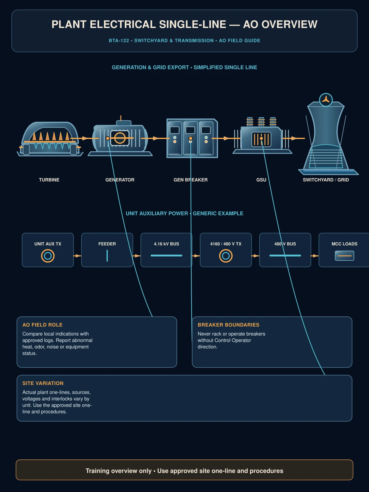
BTA-112 followed voltage from the generator down through the plant's own distribution system. This module picks up at the other end: what happens after the Generator Step-Up transformer, where the plant's power enters the switchyard and connects to the wider transmission grid. The switchyard is technically often owned or operated by the transmission utility or grid operator rather than the plant itself, but Auxiliary Operators still need to understand it — plant output physically flows through it, and switchyard conditions directly affect the plant.
Everything in this module operates at transmission voltage — hundreds of kV. This is meaningfully more dangerous than even the 4160V switchgear from BTA-112. Your role around switchyard equipment is almost always observational; switching operations here are typically performed by specifically qualified personnel, sometimes not even plant employees.
Disconnect Switches
A disconnect switch (or "isolator") provides a visible, physical break in a circuit. Most disconnects you'll encounter are not designed to interrupt load current — they're operated only when the circuit is already de-energized (typically after the associated breaker has already opened). Some specialized load-break or load-interrupter switches are built to open under load, but never assume this without confirming the specific equipment's rating — treat every disconnect as unable to interrupt load unless your plant's equipment documentation and procedure explicitly say otherwise. Disconnects provide a visually verifiable open point for safety purposes, similar in spirit to racking out a breaker in BTA-112, but at transmission voltage and scale.
Opening a disconnect switch under load can cause a severe arc flash and equipment destruction — disconnects are built for isolation, not interruption. This is why switching sequences always open the breaker first, then the disconnect.
Bus Configurations
The switchyard bus is the common electrical connection point tying together incoming plant generation and outgoing transmission lines. Different bus configurations (ring bus, breaker-and-a-half, single/double bus arrangements) offer different tradeoffs between cost, reliability, and flexibility to isolate individual pieces of equipment for maintenance without taking the whole switchyard out of service. More redundant configurations cost more to build but allow more maintenance flexibility and fewer forced outages.
Instrument Transformers: CTs and PTs
Current Transformers (CTs) and Potential (Voltage) Transformers (PTs) step down transmission-level current and voltage to safe, standardized levels that protective relays and metering equipment can actually use — you obviously can't wire a relay directly into a transmission line. These instrument transformers are what make transmission-level protection and metering possible at all.
Transmission Protective Relaying
Transmission-level protection extends the protective relay concepts from BTA-112 to a much larger, more consequential scale — a fault on a transmission line can affect grid stability across a wide area, not just one plant. Transmission relaying often includes additional sophistication like directional protection (determining which direction a fault is located relative to the relay) and communication-based schemes that coordinate protection between multiple substations to isolate a fault as precisely and quickly as possible.
Surge/Lightning Arresters
Transmission equipment is exposed outdoors and vulnerable to lightning strikes and switching surges — sudden, brief voltage spikes that could otherwise damage expensive equipment like transformers. Surge arresters provide a controlled path for that excess voltage to safely discharge to ground, protecting equipment from transient overvoltage events.
Grounding at Switchyard Scale
Switchyard grounding extends the grounding concepts from BTA-108 to a much larger scale — an extensive underground grid of grounding conductors beneath the entire switchyard, keeping step and touch potentials safe for anyone in the area during a fault. Grounding switches are a specific application: temporary, visible grounds applied to a de-energized line or bus section during maintenance, providing certainty that stored or induced voltage can't create a hazard — conceptually similar to LOTO's zero-energy verification, but for high-voltage equipment.
SCADA and Grid Operator Visibility
Switchyard status and readings feed into SCADA (Supervisory Control and Data Acquisition) systems that the grid operator (ISO/RTO, introduced in the plant-type modules) uses to monitor and, in some cases, remotely operate switchyard equipment. This is part of why switchyard conditions matter to the plant beyond the physical equipment itself — actions here are visible to, and sometimes controlled by, an external party coordinating grid-wide reliability.
Ready to test what you just learned?